|
This Tk coding structure is discussed in more detail on the page
A Canonical Structure for Tk Code --- and variations.
This makes it easy for me to find code sections --- while generating
and testing this script, and when looking for code snippets to
include in other scripts (code re-use).
One new thing that I have started doing in 2013 is using a text-array
for text in labels, buttons, and other widgets in the GUI.
This can make it easier for people to internationalize my scripts.
I will be using a text-array like this in most of my scripts
in the future.
Experimenting with the GUI
As in all my scripts that use the 'pack' geometry manager
(which is all of my 100-plus scripts, so far), I provide
the four main 'pack' parameters
--- '-side', '-anchor', '-fill', '-expand' --- on all
of the 'pack' commands for the frames and widgets.
That helps me when I am initially testing the behavior of a GUI
(the various widgets within it) as I resize the main window.
I think I have found a nice combination of the pack parameters.
The listbox and its scrollbars expand/contract when the
window is resized --- while the label and button widgets
stay fixed in size and relative location.
You can experiment with the '-side', '-anchor', '-fill',
and '-expand' parameters on the 'pack' commands for the various
frames and widgets --- to get the widget behavior that you want.
---
Additional experimentation:
You might want to change the fonts used for the
various GUI widgets. For example, you could change '-weight'
from 'bold' to 'normal' --- or '-slant' from 'roman' to 'italic'.
Or change font families.
In fact, you may NEED to change the font families, because
the families I used may not be available on your computer ---
and the default font that the 'wish' interpreter chooses may not
be very pleasing.
I use variables to set geometry parameters of widgets ---
parameters such as border-widths and padding. And I have included
the '-relief' parameter on the definitions of frames and widgets.
Feel free to experiment with those 'appearance' parameters as well.
Some features of the code
That said, here's the code --- with plenty of comments to describe
what most of the code-sections are doing.
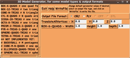
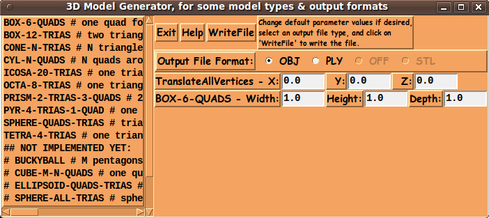
One of the rather unusual features of this script is the fact that
the 'parameters' frame is changed according to the 'model-type'
selected.
For example:
-
When 'BOX-6-QUADS' is selected, the 'parameters' frame prompts for the
3 parameters width, height, and depth.
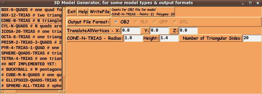
-
When 'CONE-N-TRIAS' is selected, the 'parameters' frame prompts for
3 different parameters --- 'radius' and 'height' and 'N' (the number of
triangles to be used to make the 'side' of the cone).
You can look at the procs
'load_parameters_frame_BOX6QUADS'
and
'load_parameters_frame_ICOSA20TRIAS'
to see how the pack forget command is used to change the widgets in
the 'parameters' frame.
Those 'load_parameters_frame_XXX' procs also enable or
disable the 'output-type' radiobuttons on the GUI to correspond to
the currently available 'write' procs for any selected 'model-type'.
You can use the 'Help' button on the GUI to see information on how
to add a 'model-type' to this utility.
It involves adding a 'load_parameters_frame_XXX' proc and at least one
'write_model_XXX_YYY' proc to the script.
The bottom of the 'Help' also describes the formats of OBJ, PLY, OFF,
and STL files --- and the help describes which parts of the format
specifications are being supported by these 'writers'.
It is my hope that the copious comments in the code will help Tcl-Tk
coding 'newbies' get started in making GUI's like this --- and perhaps
have some fun with the 'pack forget' command.
Without the comments, potential young Tcler's might be tempted to
return to their iPhones and iPads and iPods --- to watch
Earth's/Jupiter's/Uranus's Funniest Home Videos.
The Code
Here is a link to CODE for the script
'3DmodelGenerator.tk'.
Setting the Text Editor
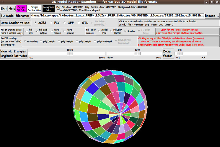
Another not-so-common feature of this Tk script --- besides the
'pack forget' technique that is used to 'dynamically' change
the parameters frame in the GUI --- is that, after the model
file is written, the file is displayed to the user in a GUI text
editor of the user's choice.
You can see in the text of the 'HELPtext' variable, set at the bottom
of the script above, that the user can edit the 'set' statement for
variable 'EDITOR_text', near the bottom of the script,
to set the text-editor to be the user's preferred editor.
The editor is called up from within the Tk script by using the
Tcl 'exec' command.
---
The 'writers' are so fast that IMMEDIATELY after clicking on the
'WriteFile' button, the text-editor pops up displaying the model file.
Some Possible Enhancements
One thing that concerned me as I wrote this utility is that
the script was greatly increasing in size as I added each
polygon-type --- because the vertex-coordinates and the
vertex-connectivity information of each model was
stored in arrays in the script.
If I ever revise this script, I will probably store the
model geometry for each 'shape' in a file containing
'base' or 'unit' coordinates for the vertices ---
and the face connectivity information --- say,
in OBJ file format.
Then, when the user selects a 'shape' from the listbox,
the 'base' model file will be read in and various
transformations applied (translation, magnification,
rotation) --- according to parameters entered on the GUI.
So, if you find this utility of use, you may want to check back
here in coming years to see if an updated
version of the script is available.
Other possible enhancements/additions:
CONCLUSION
It takes several days to get model-generating code like this in shape.
But, once implemented, I am in a position to generate model files
(of various sizes and shapes and numbers of polygons/ponts)
at about 30 microseconds per model file, instead of more than
30 minutes per model file. :-) :-) :-) :-) :-)
Thank you, Tcl-Tk developers, for making it possible for
me to make nice quality images of geometry in 3-space.
UPDATE 2013jan27
I changed the GUI rather significantly by changing the model-type selection
from using a couple of rows of radiobuttons to a using a listbox on the
left of the GUI.
This facilitates adding many, many more 'model-types'.
(I updated the text and images above accordingly.)
I can also add more description of each model-type, by taking advantage
of the x-scroll-bar of the listbox.
The y-scroll-bar allows for an unlimited number of added 'model-types'.
I have replaced the two GUI images above with the new images, and
I have replaced the code above with the new code.
You can see the 'set' statement for the 'HELPtext' variable,
near the bottom of the script, for a description of how to
add new 'model-types' to the listbox.
Some 'model-types' that I have not implemented yet can be
seen in the listbox of the images above. They are indicated
by a hash-sign (a comment-sign) at the beginning of those listbox lines.
Over the coming months/years, I may implement more of those
'model-types'.
To accomodate a large number of types of models
--- and to avoid putting a lot of model geometry data in
the script, I may change the script to read from
a library of model files --- and apply transformations
to those 'unit' models --- such as magnification,
translation, and rotation of coordinates --- to create
a new model file --- say, in OBJ format.
|