FE 'tkGooie' Utilities

'IMAGEtools' group

'Grid Warp
an Image'

(keeping the image
edge-pixels fixed)

(FE = Freedom Environment)

The FE 'Grid Warp' or 'wheeeWarp'
'tkGooie' interface.

It reads a user-specified GIF or PNG file.

FE Home Page > FE Downloads Page >

FE 'tkGooies' Description Page >

FE 'tkGooies' 'IMAGEtools' Page >

This 'Grid Warp an Image' tkGooie IMAGEtool Page

INTRODUCTION to
'tkImageGridWarp_withFixedEdge'

For about a year (from early-2013 to early-2014), I had an 'image-warp-via-grid' item on my 'to-do' list.

My intent was to use a rectangular grid but to do the 'color mapping' from the original image onto the warped grid via triangles in the rectangles/quadrangles --- by using 'barymetric coordinates'.

Back on 2013sep05, I posted code on wiki.tcl.tk that used a barymetric technique --- on a page with the title '3-Color-Gradient Isosceles Triangle - Barymetric Blend with Shaded Edges'.

On that color-shaded-isoceles-triangle page, I presented a Tk script that peforms a color blend using barymetric coordinates.

I knew that I could use similar mathematics to do the 'grid-warp' of a given image using 'barymetric coordinates' on triangles --- to associate pixels in a 'moved triangle' to pixels in the corresponding, original, not-moved triangle (and the underlying, original image).

See that wiki page above (#38676) for details on the barymetric mathematics involved and for further sources on barymetric coordinates and math.

Or, better, see the perhaps-more-up-to-date version of that page on this site.

---

THE GOALS

My main goals for the 'image warp' Tcl-Tk script were:

  1. Provide a GUI for selecting an image file --- GIF or PNG.

      (JPEG or about 100 other types of image file could be translated to one of these types for use in this utility --- for example by using the ImageMagick 'convert' command.)

  2. Provide a grid of movable points, for the user to define the warp.

  3. Provide the user a way to easily change the grid to have a different number of 'segments' in the x and y directions.

  4. Provide a way to easily hide the grid (points and lines), so that the warped image can be captured without the grid showing.

  5. Devise the procs in the script in a modular fashion, so that essentially any operation can be done by the user, in almost any order, and reasonable results/responses will be obtained.

(I am currently not concerned with handling transparency in GIF and PNG images. So, in the code below, I have not included code to handle transparency information in either of those 2 types of image file.)


SCREENSHOT OF THE GUI

On the basis of the goals above (and after many days of coding and testing --- and re-designing and re-coding and re-testing --- and almost giving up), I ended up with the GUI seen in the following image.

Note that there are two entry fields in which to set the parameters 'Nxsegs' and 'Nysegs' that control the 'fineness' of the grid.

Also note that there are a couple of 'label' widgets across the middle of the GUI --- one label for giving a brief guide on how to load an image to the canvas (with a grid) --- and one 'status' label to allow for communicating to the user how the warp processing is going.

---

TYPICAL SEQUENCE OF OPERATIONS WITH THE GUI

STEP 1:

Select the image file to be warped. This is most conveniently done with the 'Browse...' button on the GUI.

STEP 2:

As indicated in a brief 'guide' on the GUI, the user can 'right-click' (with mouse-button-3) on the filename entry field to cause the image file to be read and its image shown on the 'canvas'.

STEP 3:

The 'fineness' of the grid can be set via 'Nxsegs' and 'Nysegs' entry fields on the GUI --- which specify the number of grid 'segments' in the x and y directions.

The grid consists of (Nxsegs + 1) times (Nysegs + 1) points. For example, if Nxsegs = 20 and Nysegs = 10, there are 21 x 11 = 231 points in the rectangular grid --- and 20 x 10 = 200 rectangles.

(Also 2 * (20 x 10) + 20 + 10 = 430 lines are drawn in the grid.)

You can button1-Press-and-Hold on the '+' and '-' buttons beside the Nxsegs and Nysegs entry fields to change the numbers rather rapidly --- but not so rapidly that they advance more than one unit at a time.

Or you can simply enter numbers in those two fields. Then, like the filename entry field, 'right-click' (mouse-button3-release) or use the Return key to cause the new segments number(s) to be applied. A new grid will be built on the canvas.

STEP 4:

The user moves one or more grid points, by clicking on the canvas near a grid point and dragging the grid-point with mouse-button-1.

When done moving a set of grid points, click on the 'WarpAtMovedPts' button to cause the image to be warped according to all the grid points that were moved.

Repeat these steps as needed.

If things get confusing, the user can click on a 'ClearCanvas' button, then reload the image file to the canvas (with a 'right click' on the filename entry field) and start fresh.

---

When one goes through these steps and gets a warped image, it can be nice to compare the warped image to the original image.

The 'FlashOrigImg' button is meant to accomplish this --- by showing the original image over the warped image for a couple of seconds, and then removing it.

---

USING THE WARPED IMAGE:

To keep the GUI relatively simple, there is no 'SaveAs-GIF/PNG/JPEG' button on the GUI --- as seen in the images above.

A SCREEN/WINDOW CAPTURE UTILITY (like 'gnome-screenshot' on Linux) can be used to capture the GUI image in a PNG file, say.

Note that you can use the 'ShowGridPoints' and 'ShowGridLines' checkbuttons on the GUI to turn off the display of the grid on the image, before doing an image capture.

If necessary, an image editor (like 'mtpaint' on Linux) can be used to crop the window-capture image. The image could also be down-sized --- say, to make a smaller image suitable for a web page or an email. And the image could be converted from PNG to GIF or JPEG --- for example, by using the ImageMagick 'convert' command.


MAKING ANIMATED GIF's:

Note that given a warped image, one could make an animated GIF --- which flashes back and forth between the original image and the warped image.

For example, the 2 images could be combined to make an animated GIF --- using a program like ImageMagick 'convert'. Example command:

convert -delay 100 -loop 0 file1 file2 output_ani.gif

where the delay time of 100 is in 100ths of seconds, giving an inter-image wait time of 1.0 seconds. The parameter '-loop 0' indicates that the animated GIF file should be played indefinitely, rather than stopping after a finite number of cycles.

In fact, that is what I have done with the image seen in the screenshot above.

Here is the original image.

Here is the warped image, that I captured using the technique outlined above --- 'gnome-screenshot' with the 'mtpaint' image editor used to crop the image.

And here is the resulting animated GIF file.

By using this 'tkImageGridWarp' utility, we can help this person button those too-small jeans.


DESCRIPTION OF THE CODE

Below, I provide the Tk script code for this 'grid-warp-an-image' utility.

I follow my usual 'canonical' structure for Tk code for this Tk script:


  0) Set general window & widget parms (win-name, win-position,
     win-color-scheme, fonts-for-widgets, widget-geometry-parms,
     text-array-for-labels-etc, win-size-control).

  1a) Define ALL frames (and sub-frames, if any).
  1b) Pack   ALL frames and sub-frames.

  2) Define & pack all widgets in the frames, frame by frame.
              Within each frame, define ALL the widgets.
              Then pack the widgets.

  3) Define keyboard and mouse/touchpad/touch-sensitive-screen action
     BINDINGS, if needed.

  4) Define PROCS, if needed.

  5) Additional GUI initialization (typically with one or more of
     the procs), if needed.


This Tk coding structure is discussed in more detail on the page A Canonical Structure for Tk Code --- and variations.

This structure makes it easy for me to find code sections --- while generating and testing a Tk script, and when looking for code snippets to include in other scripts (code re-use).

I call your attention to step-zero. One thing that I started doing in 2013 is use of a text-array for text in labels, buttons, and other widgets in the GUI. This can make it easier for people to internationalize my scripts. I will be using a text-array like this in most of my scripts in the future.


EXPERIMENTING WITH THE GUI

As in all my scripts that use the 'pack' geometry manager (which is all of my 100-plus scripts, so far), I provide the four main pack parameters --- '-side', '-anchor', '-fill', '-expand' --- on all of the 'pack' commands for the frames and widgets.

That helps me when I am initially testing the behavior of a GUI (the various widgets within it) as I resize the main window.

I think that I have used a pretty nice choice of the 'pack' parameters. The label and button and checkbutton widgets stay fixed in size and relative-location if the window is re-sized --- while the filename entry widget expands/contracts horizontally whenever the window is re-sized horizontally.

And the canvas expands both horizontally and vertically when the window is resized.

For example, if the user clicks on the Maximize button of the window, the window-manager expands the window to screen-size --- and the filename entry field expands to maximum size horizontally, and the canvas expands to maximum size both horizontally and vertically.

You can experiment with the '-side', '-anchor', '-fill', and '-expand' parameters on the 'pack' commands for the various frames and widgets --- to get the widget behavior that you want.

---

Additional experimentation: You might want to change the fonts used for the various GUI widgets. For example, you could change '-weight' from 'bold' to 'normal' --- or '-slant' from 'roman' to 'italic'. OR change font families.

In fact, you may NEED to change the font families, because the families I used may not be available on your computer --- and the default font that the 'wish' interpreter chooses may not be very pleasing.

I use variables to set geometry parameters of widgets --- parameters such as border-widths and padding. And I have included the '-relief' parameter on the definitions of frames and widgets. Feel free to experiment with those 'appearance' parameters as well.

If you find the gray 'palette' of the GUI is not to your liking, you can change the value of the RGB parameter supplied to the 'tk_setPalette' command near the top of the code.


SOME FEATURES IN THE CODE

The code has plenty of comments to describe what most of the code-sections are doing.

You can look at the top of the PROCS section of the code to see a list of the procs used in this script, along with brief descriptions of how they are called and what they do.

The main procs are :


   'get_img_filename'      - called by the 'Browse...' button beside
                             the entry field for the image file.

   'get_chars_before_last' - called by procs 'get_img_filename' and
                             'checkFile_convertToGIF'.

   'checkFile_convertToGIF' - called by proc 'get_img_filename'. This is
                              the proc that accepts a non-GIF file and
                              makes a '.gif' file from it.

   'load_file_to_canvas'   - called by button1-release or  on
                             the filename entry field.

 The following 6 procs are called by 'load_file_to_canvas', to get started.

   'create_photoID0'       - called by procs 'load_file_to_canvas'.

   'create_photoID1'       - called by proc 'load_file_to_canvas'.

   'set_scrollregion_size' - called by proc 'load_file_to_canvas'.

   'put_img1_on_canvas'    - called by procs 'load_file_to_canvas'.

   'initialize_grid_arrays' - called by procs 'load_file_to_canvas'.

   'draw_grid1'            - called by procs 'load_file_to_canvas'.

  Note that if one wants to RESTART with a new image --- by changing the
  image data in the named image file, or by switching to a new image filename
  --- the RESTART can be effected by running the above 6 procs again ---
  by simply calling the 'load_file_to_canvas' proc.

  We should also consider which of the above procs should be rerun
  when the x,y grid-segments entries are changed. Note that changing
  x,y grid-segments requires rerunning the last two procs ---
  'initialize_grid_arrays' and 'draw_grid1'.

 The following 3 procs handle moving a grid-point.

   'move_pointSelect'  - called by a button1-press   binding on a point-tag of the canvas.
   'move_point'        - called by a button1-motion  binding on the canvas.
   'move_pointEnd'     - called by a button1-release binding on a point-tag of the canvas.

   'delete_lines_at_ij'    - called by proc 'move_pointEnd', to delete
                             the 4 lines connected to the moved grid-point.

   'redraw_lines_at_ij'    - called by proc 'move_pointEnd', to redraw
                             the 4 lines connected to the moved grid-point.

 The following 3 procs handle the warping.

 'warp_at_moved-points' - called by 'WarpAtMovedPts' button. Calls the 'warp_inQuad'
                          proc in a loop.

   'warp_inQuad'       - called by the 'warp_at_moved-points' proc.

                         This proc is called in 'warp_at_moved-points' for each
                         'grid1' quadrangle that has been changed.

                         At a changed quadrangle, this 'warp_atQuad' proc
                         makes a new image 'barymetrically' --- using 2 triangles
                         in the indicated quadrangle.

                         See rough diagram of the triangles in comments in this code.

                         For a given one of the triangles,
                         the barymetric warp is done by a 'barymetric mapping' between
                         the 'moved triangle' and the corresponding unwarped triangle
                         on the original stored stored image.

                         The pixels in the 'moved triangle' are 'colored' according
                         to the corresponding pixels in the unwarped triangle on the
                         original image.

  'fill_grid1_triangle_with_corners'  - called by the 'warp_inQuad' proc,
                                        to handle the barymetric color-mapping
                                        for each triangle. This is where the
                                        barymetric math resides.

  This proc lets the user see the original image:

   'flash_orig_img'         - called by the 'FlashOrigImg' button.

 The following 4 procs handle the '+' and '-' buttons beside the
 Nxsegs and Nysegs entry fields.

   'incr_nxsegs'       - called by button1-press binding on Nxsegs '+' button
   'decr_nxsegs'       - called by button1-press binding on Nxsegs '-' button
   'incr_nysegs'       - called by button1-press binding on Nysegs '+' button
   'decr_nysegs'       - called by button1-press binding on Nysegs '-' button

   'reload_grid'  - called by button3-release or Return bindings on the
                    Nxsegs and Nysegs entry fields.

 The following 2 procs handle the Show Points/Lines checkbuttons.

 'hide-show_grid_points' - called by button1-release binding on the points checkbutton
 'hide-show_grid_lines'  - called by button1-release binding on the lines checkbutton


   'popup_msgVarWithScroll' - used to show messages to the user, as well as
                              the HELPtext for this utility via the 'Help' button.


Modularity of procs

One of the trickiest things about this GUI involved finding a way to break up the necessary operations into a 'modular' form in the procs --- so that the groups-of-operations would support the various user-actions that might be needed via the GUI widgets.

Comments at the top of the code indicate how I outlined the sequence of operations to be implemented and how I grouped those operations into separate procs.

Even if it is necessary to change, somewhat, the way the operation-groups are performed via 'events' on the widgets of the GUI, the 'granularity' of the modular break-down of the operations into procs will probably serve to facilitate a relatively easy change to accomodate the necessary operations triggered by any particular widget-event.

---

JPEG and PNG (and other non-GIF image formats)

Another challenge was to be able to handle JPEG and PNG files as well as GIF files --- without requiring the user to install a '3rd party' Tk-extension to handle reading JPEG files --- or to install Tk 8.6 to handle reading PNG files.

I settled on using the 'exec' command to issue the ImageMagick 'convert' command.

Code fragment in proc 'checkFile_convertToGIF':


  set RETcode [catch {exec convert "$INfilename" -colors 256 "$tempFilename"} CatchMsg]


where 'tempFilename' contains a name that ends with '.gif'.

In fact, the proc 'checkFile_convertToGIF' includes an 'exec' of the 'file' command to determine if the $INfilename file is a GIF file --- via use of the Tcl 'string match' command.

If the file is determined to be a GIF file, then 'convert' is not used. But, for any other file, the file is converted to a GIF file.

So this utility will actually warp any of the 100-plus types of image file supported by the ImageMagick 'convert' command --- by converting such files to a new '.gif' file. Reference: http://www.imagemagick.org/script/formats.php

So this utility will convert PGM (Portable Gray Map), PPM (Portable Pixel Map), TIFF (Tagged Image File Format), TGA (Targa), XWD (X Window Dump) and other types of image files to '.gif' files --- and do the warp with those GIF files.

---

"Flashing" the original image

Implementation of the 'flash-the-original-image' option (when the user clicks on the 'FlashOrigImg' button) was done by the following statements in proc 'flash_orig_img':


   .fRcanvas.can create image 0 0 -anchor nw \
      -image $IDimg0 -tag TAGimg0

   update

   after 2000

   .fRcanvas.can delete TAGimg0


This puts the in-memory image 'IDimg0' onto the canvas and removes it after about 2 seconds. Note that it does not reload the original image into memory. This routine simply refers to the already-loaded image.


Handling huge images

To be able to scroll huge images, a '-scrollregion' parameter is used to configure the (scrollable) canvas --- in proc 'set_scrollregion_size'.


There are probably other noteworthy 'features' of the code that could and should be mentioned here.

In fact, it would probably be helpful to provide some 'lessons learned' about

  • the 'move_point' procs and their bindings to tag or canvas

  • the need to keep the grid-points 'above' the grid-lines, so that the grid-lines do not interfere with selecting a grid-point to move.

There are a few comments in the code on these issues, but they deserve a little more discussion. However, this 'features of the code' section is long enough as is. Enough for now.


It is my hope that the copious comments in the code will help Tcl-Tk coding 'newbies' get started in making GUI's like this.

Without the comments, potential young Tcler's might be tempted to return to their iPhones and iPads and iPods --- to watch videos of Steven Colbert imitating his hero --- Bill O'Reilly.


The Tcl-Tk CODE

Here is a link to CODE for the script 'tkImageGridWarp_withFixedEdge.tk'.


INSTALLING THE UTILITY/APP:

This utility/app consists of ONE Tk script.

This script could be put in a sub-directory of the user's home directory, such as $HOME/apps/tkImageGridWarp.

Then the user can use his/her desktop system (such as Gnome or KDE) to set up the main Tk script as an icon on the desktop (or in a desktop 'panel').

Then, whenever the user wants to warp an image, he/she can click on the icon to startup the 'grid-warp-image' GUI.


SOME POSSIBLE ENHANCEMENTS

In using this utility over the next year, I may find that I would like to add a few capabilities, such as

1) Add a 'MakeAniGIF' button to make an animated GIF from the original image and a warped image (in about a second) --- to 'transition' repeatedly, back-and-forth between the two images.

The user could be given options to specify --- such as wait-time between frames. Another option could be a choice of the utility to use to make the animated GIF. For example, either ImageMagick 'convert' or 'gifsicle' could be used to make the animated GIF file.

After making a warped image, making the animated GIF would be as easy as clicking on the 'MakeAniGIF' button.

2) Allow for handling transparency in a selected image file (for GIF and PNG files).

3) Allow for 'SLIDING' the 'edge' grid points along the edges of the image --- or even pulling them 'INWARD'. However, the grid-handling code then becomes quite a bit more complex. So it might be good to keep this script intact and make a new 'tkImageGridWarp_withSemiFixedEdge.tk' script.

An even more enhanced script would allow for a background-color margin around the image and allow for pushing the 'edge' grid points 'OUTWARD'.

---

Handling All the Things a User Could Do With the GUI
(and ... 90-plus% of the code is there)

I have tried quite a few different operations with the GUI, such as:

* loading one image, then a different (sized) image

* starting with the default grid, then changing Nxsegs and Nysegs

* turning the grid on and off.

I resolved quite a few issues in the process, but there are probably a few remaining. However, I rejoice that 95% to 99% of the code is in place to achieve the goals I had in mind. Any further fixes and enhancements will probably feel like nothing compared to what I have been through in developing and testing this script.

The writing and testing of this script rivals the amount of effort that I had to expend in developing the 3D model viewing script on a page named A 3D Model File Loader-and-Examiner - for OBJ, PLY, OFF, STL, FEA files.

There is certainly a lot more challenge in creating a 'robust' interactive Tk script than there is in making a 'demo' Tk script in which a sequence of operations is basically hard-coded in the script --- thus making it unnecessary to handle essentially anything a user might do with a GUI that has quite a few control widgets on it.

---

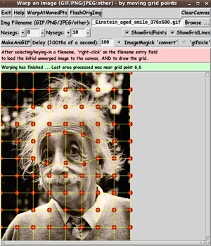
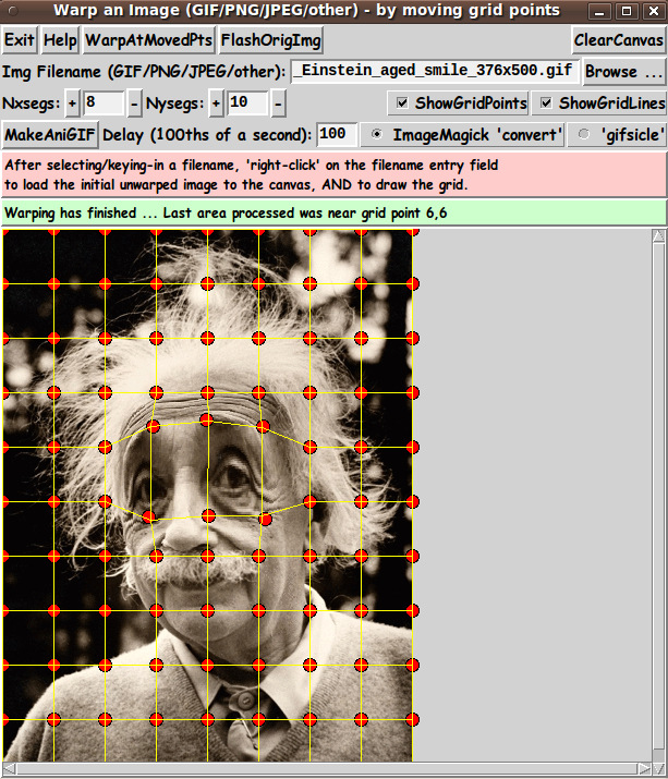
By the way, I notice an 'artifact' in the sample warped image above. I think I need to make a change in technique used in one of the procs in the 3-proc hierarchy of 'warping' procs. I will probably make an improvement in the code above and post an improved test image (and animated GIF) within the next few weeks (before May 2014). The change will probably not increase the lines/characters of code at all. There might be a slight decrease.


IN CONCLUSION

As I have said on several other code-donation pages on this FE site ...

There's a lot to like about a utility that is 'free freedom' --- that is, no-cost and open-source so that you can modify/enhance/fix it without having to wait for someone else to do it for you (which may be never).

A BIG THANK YOU to Ousterhout for starting Tcl-Tk, and a BIG THANK YOU to the Tcl-Tk developers and maintainers who have kept the simply MAH-velous 'wish' interpreter going.


2014mar25 UPDATE

I indicated above in the 'Possible Enhancements' section that there was an 'artifact' in an image and an animated GIF above. I said I would revise the code to fix the cause of the artifact and replace the 2 images and the code. I have done that.

And to demonstrate that the above image was not a 'fluke', here is another example --- using W. C. Fields.

He was known to have a large nose, later in life. Here is a photo of him at that time.

Here is a warping grid that I put on that photo --- to reduce the size of his nose and to put a little bit of a smile on his face.

Here is the resulting warp. (I could have made the new nose at the original angle instead of so vertical. Maybe next time.)

And here is an animated GIF made from the original image and a single warped image.

I am relieved that after much, much work, I got it to work.


2014mar27 UPDATE

In the 'Possible Enhancements' section above, I indicated that I might add a 'MakeAniGIF' button. I have done that --- in an added '.fRanigif' frame, using an added 'make_aniGIF' proc.

A Delay-time entry widget and a couple of radiobuttons were added to the GUI, in the new '.fRanigif' frame. Image below.

I have updated the 'HELPtext' variable with the following mini-guide:


  To make it easy for the user to make a TWO-IMAGE animated-GIF
  --- from an original image and a warped image --- the GUI
  has a 'MakeAniGIF' button.
  
  After the user performs a warp, the user can SIMPLY click on
  the 'MakeAniGIF' button. 'Underneath the covers', this utility
  makes two GIF files in a temporary directory --- from the
  original image and the warped image (that are in-memory).
  
  By default, this utility uses the ImageMagick 'convert' command
  to make an animated GIF from the two GIF files --- using the
  'Delay' parameter on the GUI to determine the length of time
  each image is displayed.
  
  Alternatively, the user can use the 'gifsicle' command by
  changing the radiobuttons setting on the GUI.
  
  So that the user does not have to navigate to the temporary
  directory to see the files, the animated GIF is IMMEDIATELY
  shown to the user in animated mode.
  
  If ImageMagick 'convert' was used, the animated-GIF is shown
  with the ImageMagick 'animate' command.
  
  If 'gifsicle' was used, the animated-GIF is shown with the
  'gifview' command, which often comes with 'gifsicle'.
  
  If the animated-GIF file is usable, the user can navigate
  to the temporary directory (defaulted to /tmp) and find
  the '_ani.gif' file there. Move it and/or rename it.


The following image shows the new GUI --- with the new 'MakeAniGIF' button, 'Delay' entry field, and 'convert'/'gifsicle' radiobuttons.

You can see a warped grid and the warped image underneath it --- the result of clicking on the 'WarpAtMovedPoints' button.

Clicking on the 'MakeAniGIF' button created and showed the following animated GIF --- in a fraction of a second.

Even Einstein was surprised when told that one of his predictions was proven true.

I feel that this utility/app is pretty complete now. HOWEVER, the 'MakeAniGIF' feature only uses the original image and the warped image. It does not create a sequence of images ---- which would be helpful to make a smoother looking transition, especially in cases where the warped image differs appreciably from the original image.

I got some experience in making a sequence of grids that 'linearly interpolate' between 2 given grids --- in making a 'wheeeMorph' utility. I could add an 'Nframes' prompt to this 'ImageGridWarp' GUI and use a similar technique to have the 'MakeAniGIF' button make animated-GIF files composed of more than 2 images.

If I were to enhance this utility further, I would probably make a new script that put a solid-colored background margin around a loaded image and allow the user to move the outer-edge grid points --- both inward and outward.

A somewhat less ambitious enhancement would be to allow the user to 'slide' grid points along the edges, but NOT allow the edge grid points to be moved 'outward' or 'inward'.

Bottom of this page for
'Grid Warp an Image'
(keeping image edge pixels fixed)
--- a utility in the FE 'tkGooies' system,
in the 'IMAGEtools' group.

To return to a previously visited web page location, click on the Back button of your web browser a sufficient number of times. OR, use the History-list option of your web browser.
OR ...

< Go to Top of Page, above. >

Page history:

The code was created in 2014 --- and posted 2014 Mar 24 at http://wiki.tcl.tk/39587.

This FE web page was created 2014 May 07 --- as a backup and alternative to the wiki.tcl.tk page.

This page was changed slightly 2015 Oct 05.
(Small changes.)

Page was changed 2019 Feb 25.
(Added css and javascript to try to handle text-size for smartphones, esp. in portrait orientation.)

Page was changed 2019 Jun 13.
(Specified image widths in percents to size the images according to width of the browser window.)


NOTE:
The code here MAY BECOME more 'up-to-date' than the code posted on the Tcler's Wiki ---
wiki.tcl-lang.org --- formerly wiki.tcl.tk.