FE 'tkGooie' Utilities
'IMAGEtools' group
'wheeeMorph'
tool
(FE = Freedom Environment)
The FE 'wheeeMorph'
'tkGooie' interface.
It reads in user-specified
GIF or PNG files.
FE 'tkGooie' Utilities'IMAGEtools' group
'wheeeMorph'
|
The FE 'wheeeMorph' 'tkGooie' interface. It reads in user-specified GIF or PNG files. |
FE Home Page >
FE Downloads Page >
FE 'tkGooies' Description Page >
FE 'tkGooies' 'IMAGEtools' Page >
This 'wheeeMorph' tkGooie IMAGEtool Page
|
INTRODUCTION to 'wheeeMorph' In 2014 March, I posted 2 image processing scripts on the Tcler's Wiki at wiki.tcl.tk. Those scripts are also presented on this site:
Those two utilities have the option of making an animated-GIF file from the Merge or Warp process. I had an image morphing utility on my Tcl-Tk 'to-do' list for about a year before that. Since morphing is basically a combination of warping along with merging/blending 2 images, I knew that I could 'borrow' a lot of code from the 2 scripts above to make a morphing utility. And, since the typical end result from a morphing utility is an animated-image file, I knew that the make-animated-GIF code in the Merge and Warp utilities would be of use. --- It turns out that it was more challenging than I thought. There were a lot more changes and additions than I had counted on. It took almost a man-month of work to make the utility. But, as you will see in the images down this page, I managed to get some pretty good results. --- One of the big differences between my 'tkImageGridWarp' script and this 'wheeeMorph' script is that there are 2 grids (on 2 canvases) required, rather than 1 grid (on one canvas). Also, as I got into the development, I found that when I had the pointer positioned over a grid-point in one grid, I needed to provide a way to indicate the corresponding grid-point on the other grid. And I kept finding new features (and procs) that I had to add as I did preliminary testing. --- Like the 'tkImageGridWarp' script, this 'wheeeMorph' script does the warping by doing a mapping onto a warped grid. BUT it is an 'intermediate' grid, 'interpolated' between the 2 user-deformed grids --- not a single warped grid. In the color-blending, like in the warping, I encountered a major difference: Instead of getting the color for a pixel on the 'intermediate' grid from ONE image, I had to find the color of the TWO corresponding pixels on the TWO user-deformed grids (grid1 and grid2), and blend those two colors. --- Like the 'tkImageGridWarp' script, this 'wheeeMorph' script works its way over an array of QUADRANGLES --- but on an 'intermediate' grid (grid3) between 2 user-warped grids, NOT on a single 'user-warped' grid. For a given point on the 'intermediate' grid, this utility finds the two corresponding pixels on grids 1 and 2 by using triangles (where we put two triangles in each quadrangle) --- by using 'barymetric coordinates' on each triangle. The barymetric coordinates of a point in a triangle of the 'intermediate' grid (grid3) are calculated and then used to get the location of the corresponding point in the two corresponding triangles in the two user-deformed grids (grid1 and grid2). --- Back on 2013sep05, I posted code using a barymetric technique --- at the wiki.tcl.tk page --- also available on this site, in an updated form:
On that color-shaded-isoceles-triangle page, I present a Tk script that peforms a color blend using barymetric coordinates. I used the same mathematics (and code) from that script to do the 'grid-warp' of the 'tkImageGridWarp' script --- and I used the same mathematics in this 'wheeeMorph' script. See that '3-Color-Gradient Isosceles Triangle' page (link above) for details on the barymetric mathematics involved and for further sources on barymetric coordinates and math. THE GOALS My main goals for the 'wheeeMorph' Tcl-Tk script were: 1) Provide a GUI for selecting a 2 image files (GIF, PNG, JPEG, or about 100 other types). (To make it easy on the user, my goal was to allow the 2 images to be of somewhat different sizes. This utility is to center the 2 images in the canvases and determine a 'common overlay area' on the 2 images --- and morph between the 'common overlay area' of the 2 images.) 2) Provide 2 side-by-side canvases on which to put the 2 images. 3) Provide a grid of movable points on each image in each canvas --- for the user to define the warp aspect of the 'morph'. (Allow the grid points on the outer edges to 'slide' along the edges, but not move 'inward' or 'outward'.) 4) Provide the user a way to easily change the 2 grids to have a different number of 'segments' in the x and y directions. 5) Provide a 'scale' widget on the GUI by which the user can specify a 'morph factor' with which to make a single morph image --- via a 'Do1MorphImg' button on the GUI. 6) The single morph image is mainly a way to check on the morph that may be created using the current deformation of the 2 grids. Actually, the desired end result of a 'morph' is usually to create an animation of the morph. It would be too tedious to build the animation via 'manual' creation of a sequence of images. So I wanted a 'MakeAniFile' button on the GUI, by which the user can easily create the animation with a mouse click. 7) To support making the animation, I needed to provide entry widgets by which the user can specify
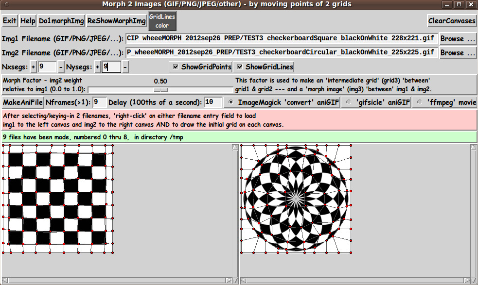
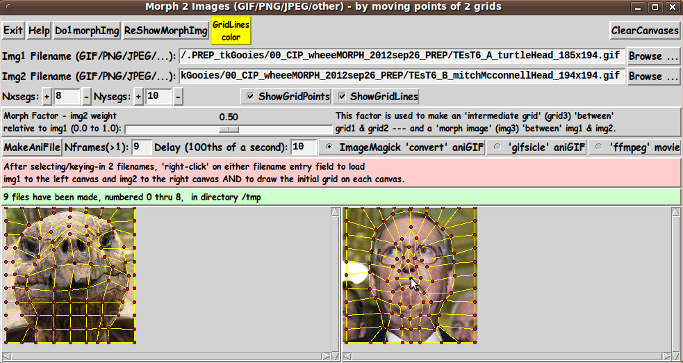
8) I wanted to provide the user the option of creating either an animated-GIF file or a movie file. (For animated-GIF's, I wanted to allow the user to use either the ImageMagick 'convert' command or the 'gifsicle' command. And for movies, eventually, I want to allow the user to use the 'ffmpeg' command --- by which an 'mp4' movie file would be created.) 9) Provide a color selector option by which the color of the grid lines can be changed. (I originally was using yellow grid lines, but one of my first pair of test images was a yellow smiley face --- happy and sad. I could not see the grid lines on the two yellow smiley faces. I realized I would need to allow the user to choose the color of the grid lines.) 10) Provide a way to easily hide the grid (points and lines), so that a single warped image can be captured without the grid showing. 11) Devise the procs in the script in a modular fashion, so that essentially any operation can be done by the user, in almost any order, and reasonable results/responses will be obtained. I am currently not concerned with handling transparency in GIF and PNG images. So, in the code below, I have not included code to handle transparency information in either of those 2 types of image file. SCREENSHOT OF THE GUI On the basis of the goals above (and after many days of coding and testing --- and re-coding and re-testing --- and re-coding and re-testing --- and wondering how many cycles of that iterative process I would have to endure), I ended up with the GUI seen in the following image. |
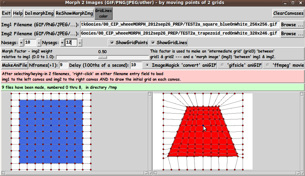
|
Below is what the GUI looks like when it first comes up --- before the user has selected 2 files to process. |
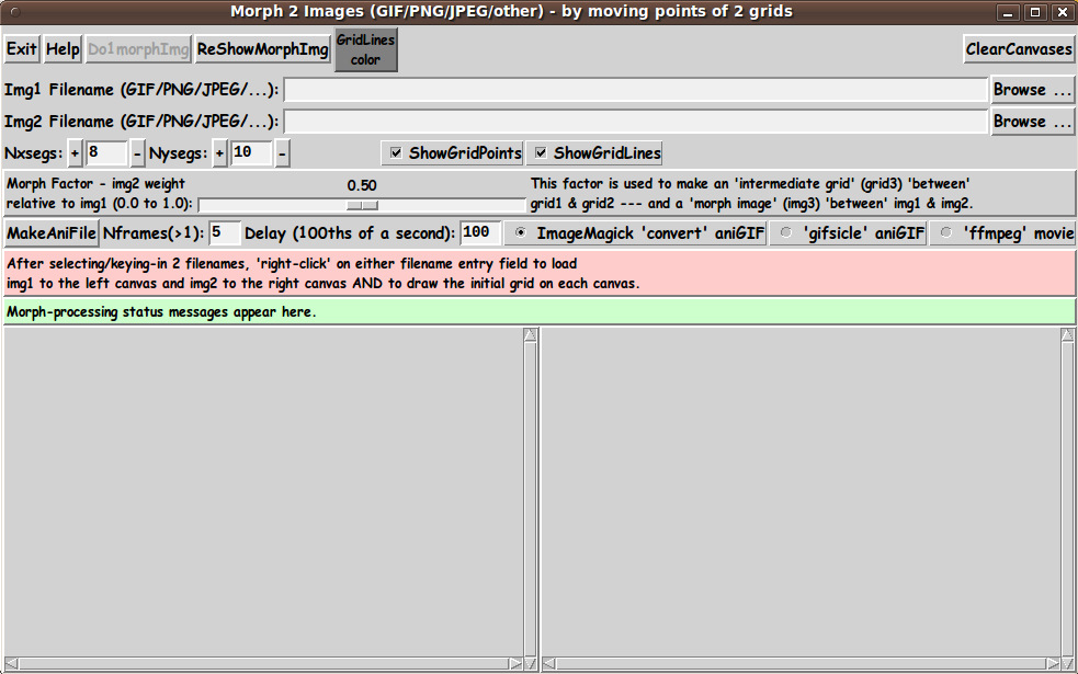
|
Note that there are two entry fields in which to set the parameters 'Nxsegs' and 'Nysegs' that control the 'fineness' of the grid. Also note that there are a couple of 'label' widgets across the middle of the GUI :
When the user clicks on the 'Do1MorphImg' button, a new window pops up, containing the morphed image and the 'intermediate' grid that was used to make it --- as seen in the following image. The morphed image is usually made within 10 seconds. |
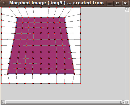
|
By clicking on the 'MakeAniFile' button, the user can make an animation --- usually within 60 seconds. |
|
Messages in the status frame of the GUI provide the user information on the frame being processed. --- TYPICAL SEQUENCE OF OPERATIONS WITH THE GUI STEP 1: Specify the 2 image files 'to be morphed'. This is most conveniently done with the 'Browse...' buttons on the GUI. STEP 2: As indicated in a brief 'guide' on the GUI, the user can 'right-click' (with mouse-button-3) on either filename entry field to cause the two image files to be read and their images shown on the two canvases. Alternatively, use the 'Return' key on either filename entry field to cause the load-and-display. STEP 3: The 'fineness' of the grid can be set via 'Nxsegs' and 'Nysegs' entry fields on the GUI --- which specify the number of grid 'segments' in the x and y directions. The grid consists of (Nxsegs + 1) times (Nysegs + 1) points. For example, if Nxsegs = 20 and Nysegs = 10, there are 21 x 11 = 231 points in each of the 2 rectangular grids --- and 20 x 10 = 200 rectangles. Also 2 * (20 x 10) + 20 + 10 = 430 lines are drawn in the grids. You can button1-Press-and-Hold on the '+' and '-' buttons beside the Nxsegs and Nysegs entry fields to change the numbers rather rapidly --- but not so rapidly that they advance more than one unit at a time. Or you can simply enter numbers in the two Nxsegs and Nysegs fields. Then, like the filename entry field, 'right-click' (mouse-button3-release) or use the Return key to cause the new segments number(s) to be applied. Two new grids will be built on the 2 canvases. STEP 4: The user moves one or more grid points, by clicking on either canvas near a grid-point and dragging the grid-point with mouse-button-1. To help associate points of grid1 with corresponding points of grid2, when the user moves the pointer over a point of either grid, both that point and the corresponding point on the other grid are changed to a new color. This makes it possible to deal with quite dense grids. When done moving a set of grid points on img1 and img2, click on the 'Do1morphImg' button to cause a 'morph image' to be created, corresponding to the current 'morph factor' setting of the 'scale' widget. The 'morph image' (img3) will be shown in a popup window in a 3rd scrollable canvas. The 'intermediate (interpolated) deformed grid' that was used to make 'img3' may be shown on img3. --- Repeat these steps as needed to get a suitable 'intermediate' image between img1 and img2. Image capture options are described below --- 'manually' for single images or 'automatic' creation of animation files. --- CAPTURING AND USING THE WARPED IMAGE: A SCREEN/WINDOW CAPTURE UTILITY (like 'gnome-screenshot' on Linux) can be used to capture the 'img3' window image in a PNG file, say. Note that you can use the 'ShowGridPoints' and 'ShowGridLines' checkbuttons on the GUI to turn off the display of the grid on 'img3', before doing an image capture. If necessary, an image editor (like 'mtpaint' on Linux) can be used to crop the window-capture image. The image could also be down-sized --- say, to make a smaller image suitable for a web page or an email. And the image could be converted from PNG to GIF or JPEG --- for example, by using the image editor or the ImageMagick 'convert' command. MAKING AN ANIMATED GIF FILE: (or movie file) Note that one could 'manually' make a sequence of 'morph images' which could be used to make an animated GIF. For example: One could make 'morph images' for 'morph factors' 0.2, 0.4, 0.6, and 0.8 and capture the 'morph image' corresponding to each 'morph factor'. Then --- after image editing (cropping or whatever) and image conversion (to GIF, say, if necessary) --- the set of captured-and-processed images, along with the original 2 images, could be combined to make an animated-GIF file --- using a program like ImageMagick 'convert' or 'gifsicle'. Example ImageMagick 'convert' command: |
convert -delay 150 -loop 0 file1 file2 file3 file4 file5 output_ani.gif
|
where the delay time of 150 is in 100ths of seconds, giving an inter-image wait time of 1.5 seconds. The parameter '-loop 0' indicates that the animated-GIF file should be played indefinitely, rather than stopping after a finite number of cycles. Alternatively, the sequence of images could be used to make a movie file with a program such as 'ffmpeg' --- with a command like: |
ffmpeg -qscale 5 -r 2 -b 9600 -i img%d.png movie.mp4
|
To make it easy for the user to make an animated-GIF (or movie) file, the GUI has a 'MakeAniFile' button. After the user sets up the warped grids on img1 and img2, the user can SIMPLY click on the 'MakeAniFile' button. 'Underneath the covers', this utility makes 'Nframes' 'morph image' files in a temporary directory --- where 'Nframes' can be specified by the user, in an entry field next to the 'MakeAniFile' button. By default, this utility uses the ImageMagick 'convert' command to make an animated GIF from the sequence of 'morph image' files that were automatically generated. The 'convert' command uses the 'Delay' parameter on the GUI to determine the length of time each image is displayed. Alternatively, the user can use the 'gifsicle' command by changing the radiobuttons setting on the GUI. OR, the user can choose to use the 'ffmpeg' command to make a movie file. So that the user does not have to navigate to the temporary directory to see the files, the animated GIF is IMMEDIATELY shown to the user in animated mode. If ImageMagick 'convert' was used, the animated-GIF file is shown with the ImageMagick 'animate' command. If 'gifsicle' was used, the animated-GIF file is shown with the 'gifview' command, which often comes with 'gifsicle'. If 'ffmpeg' was used, the movie file is shown with a movie player such as the 'mplayer' command. The user can change the player being used. See the 'make_aniFile' proc in the script. (Any of these display programs could be changed by a simple change in the 'make_aniFile' proc of the script.) If the user thinks that the animated file is usable, the user can navigate to the temporary directory (defaulted to /tmp) and find the '_ani.gif' or '.mp4' file there. Move it and/or rename it. DESCRIPTION OF THE CODE Below, I provide the Tk script code for this 'morph-2-images' utility. I follow my usual 'canonical' structure for Tk code for this Tk script: |
  0) Set general window & widget parms (win-name, win-position,
     win-color-scheme, fonts-for-widgets, widget-geometry-parms,
     text-array-for-labels-etc, win-size-control).

  1a) Define ALL frames (and sub-frames, if any).
  1b) Pack   ALL frames and sub-frames.

  2) Define & pack all widgets in the frames, frame by frame.
              Within each frame, define ALL the widgets.
              Then pack the widgets.

  3) Define keyboard and mouse/touchpad/touch-sensitive-screen action
     BINDINGS, if needed.

  4) Define PROCS, if needed.

  5) Additional GUI initialization (typically with one or more of
     the procs), if needed.
|
This Tk coding structure is discussed in more detail on the page A Canonical Structure for Tk Code --- and variations. This structure makes it easy for me to find code sections --- while generating and testing a Tk script, and when looking for code snippets to include in other scripts (code re-use). I call your attention to step-zero. One thing that I started doing in 2013 is use of a text-array for text in labels, buttons, and other widgets in the GUI. This can make it easier for people to internationalize my scripts. I will be using a text-array like this in most of my scripts in the future. EXPERIMENTING WITH THE GUI As in all my scripts that use the 'pack' geometry manager (which is all of my 100-plus scripts, so far), I provide the four main 'pack' parameters --- '-side', '-anchor', '-fill', '-expand' --- on all of the 'pack' commands for the frames and widgets. That helps me when I am initially testing the behavior of a GUI (the various widgets within it) as I resize the main window. I think that I have used a pretty nice choice of the 'pack' parameters. The label and button and checkbutton widgets stay fixed in size and relative-location if the window is re-sized --- while the filename entry widgets expand/contract horizontally whenever the window is re-sized horizontally. And the 2 canvases expand both horizontally and vertically when the window is resized. For example, if the user clicks on the Maximize button of the window, the window-manager expands the window to screen-size --- and the filename entry fields expand to maximum size horizontally, and the 2 canvases expand to a maximum size both horizontally and vertically. You can experiment with the '-side', '-anchor', '-fill', and '-expand' parameters on the 'pack' commands for the various frames and widgets --- to get the widget behavior that you want. --- Additional experimentation: You might want to change the fonts used for the various GUI widgets. For example, you could change '-weight' from 'bold' to 'normal' --- or '-slant' from 'roman' to 'italic'. OR change font families. In fact, you may NEED to change the font families, because the families I used may not be available on your computer --- and the default font that the 'wish' interpreter chooses may not be very pleasing. I use variables to set geometry parameters of widgets --- parameters such as border-widths and padding. And I have included the '-relief' parameter on the definitions of frames and widgets. Feel free to experiment with those 'appearance' parameters as well. If you find the gray 'palette' of the GUI is not to your liking, you can change the value of the RGB parameter supplied to the 'tk_setPalette' command near the top of the code. --- Note that the 'GridLines Color' button on the GUI calls on an RGB-color-selector-GUI script to set the color of grid lines. You can make that RGB-color-selector script by cutting-and-pasting the code from the page A non-obfuscated color selector GUI on this site. SOME FEATURES IN THE CODE The code has plenty of comment lines to describe what most of the code-sections are doing. You can look at the top of the PROCS section of the code to see a list of the procs used in this script, along with brief descriptions of how they are called and what they do. The procs are similar to the ones used in the 'tkImgGridWarp' script, with some additions and changes. Below is a list of most of the procs: |
   'get_img1_filename'      - called by the 'Browse...' button beside
                              the entry field for the image1 file.

   'get_img2_filename'      - called by the 'Browse...' button beside
                              the entry field for the image2 file.

   'get_chars_before_last'  - called by procs 'get_img*_filename' and
                              'checkFile_convertToGIF'.

   'checkFile_convertToGIF' - called by proc 'get_img_filename'.

   'load_2files_to_canvases'   - called by button3-release or  on
                                 a filename entry field.

 The following procs are called by 'load_2files_to_canvases', to get started.

   'load_photoID1'           - called by proc 'load_2files_to_canvases'.
   'load_photoID2'           - called by proc 'load_2files_to_canvases'.

   'set_canvas1and2_sizeANDcenter'  - called by proc 'load_2files_to_canvases'.

   'put_img1_on_canvas1'     - called by proc 'load_2files_to_canvases'.
   'put_img2_on_canvas2'     - called by proc 'load_2files_to_canvases'.

   'initialize_grid1and2_arrays' - called by proc 'load_2files_to_canvases'.

   'draw_grid1'             - called by proc 'load_2files_to_canvases'.
   'draw_grid1_points'      - called by the 'draw_grid1' proc.
   'draw_grid1_lines'       - called by the 'draw_grid1' proc.

   'draw_grid2'             - called by proc 'load_2files_to_canvases'.
   'draw_grid1_points'      - called by the 'draw_grid1' proc.
   'draw_grid1_lines'       - called by the 'draw_grid1' proc.

  Note that if one wants to RESTART with a new image --- by changing the
  image data in the named image file, or by switching to a new image filename
  --- the RESTART can be effected by running the above procs again ---
  by simply calling the 'load_2files_to_canvases' proc.

  We should also consider which of the above procs should be rerun
  when the x,y grid-segments entries are changed. Note that changing
  x,y grid-segments requires rerunning the last 3 procs ---
  'initialize_grid1and2_arrays' and 'draw_grid1' and 'draw_grid2'.

 These line-redrawing procs are called in following 'move_point' procs.

   'delete_lines1_at_ij'    - called by proc 'move_point1End', to delete
                              the 4 or 3 lines connected to the moved grid-point.

   'delete_lines2_at_ij'    - called by proc 'move_point2End', to delete
                              the 4 or 3 lines connected to the moved grid-point.

   'redraw_lines1_at_ij'    - called by proc 'move_point1End', to redraw
                              the 4 or 3 lines connected to the moved grid-point.

   'redraw_lines2_at_ij'    - called by proc 'move_point2End', to redraw
                              the 4 or 3 lines connected to the moved grid-point.

 The following 6 procs handle moving a grid-point.

   'move_point1Select'  - called by a button1-press   binding on a point-tag of canvas1.
   'move_point1'        - called by a button1-motion  binding on canvas1.
   'move_point1End'     - called by a button1-release binding on a point-tag of canvas1.

   'move_point2Select'  - called by a button1-press   binding on a point-tag of canvas2.
   'move_point2'        - called by a button1-motion  binding on canvas2.
   'move_point2End'     - called by a button1-release binding on a point-tag of canvas2.

 The following 4 procs handle hi-liting of corresponding points on canvas1 & canvas2.

   'canvas1_point_enter' - called by button1-enter binding on a point-tag of canvas1.
   'canvas1_point_leave' - called by button1-leave binding on a point-tag of canvas1.
   'canvas2_point_enter' - called by button1-enter binding on a point-tag of canvas2.
   'canvas2_point_leave' - called by button1-leave binding on a point-tag of canvas2.

 The following 3 procs create 'IDimg3'/'IDimgANI' based on the 'intermediate grid', grid3,
 which is a morph-factor-weighted linear interpolation of the corresponding points
 of grids 1 and 2.

   'set_grid3'         - called by the 'morph_over_grid' proc and the
                                       'make_aniFile'    proc below.

 'morph_over_grid'     - called by 'Do1morphImg' button. Calls the 'morph_inQuad'
                         proc in a loop.

   'morph_inQuad'      - called by the 'morph_over_grid' and 'make_aniFile' procs.

                         This proc is called in 'morph_over_grid' and 'make_aniFile'
                         for each 'grid3' quadrangle.

                         At each quadrangle of grid3, this 'morph_inQuad' proc
                         fills in pixel-colors of 'IDimg3'/'IDimgANI' in the 2 triangles
                         of the grid3 quad --- 'barymetrically'. See the
                         'fill_grid3_triangle_with_corners' proc for details.

                         See a rough diagram of the quadrangles and their triangles
                         in comments in this code.

                         For a given one of the triangles,
                         the 'barymetric morph' is done by a 'barymetric mapping' between
                         the 'intermediate triangle' of grid3 and the corresponding two
                         triangles of grid1 and grid2 on IDimg1 and IDimg2.

                         The pixels in the 'intermediate triangle' are 'colored' according
                         to a weighted-average of the 2 corresponding pixels in IDimg1 and
                         IDimg2.

  'fill_grid3_triangle_with_corners'  - called by the 'morph_inQuad' proc,
                                        to handle the barymetric color-mapping
                                        for each of the 2 triangles in the quad.
                                        Called once for each triangle.

  'min3'           - called by proc 'fill_grid3_triangle_with_corners'

  'max3'           - called by proc 'fill_grid3_triangle_with_corners'

  Here are some 'utility' procs:

  'popup_img3'              - called by the 'ReShowMorphImgAndGrid' button.

  'draw_grid3'              - called by the 'popup_img3' proc.
  'draw_grid3_points'       - called by the 'draw_grid3' proc.
  'draw_grid3_lines'        - called by the 'draw_grid3' proc.

  'make_aniFile'           - called by the 'MakeAniFile' button.

 The following 4 procs handle the '+' and '-' buttons beside the
 Nxsegs and Nysegs entry fields.

   'incr_nxsegs'       - called by button1-press binding on Nxsegs '+' button
   'decr_nxsegs'       - called by button1-press binding on Nxsegs '-' button
   'incr_nysegs'       - called by button1-press binding on Nysegs '+' button
   'decr_nysegs'       - called by button1-press binding on Nysegs '-' button

   'reload_grid1and2'  - called by button3-release or Return bindings on the
                         Nxsegs and Nysegs entry fields.

 The following 2 procs handle the Show Points/Lines checkbuttons.

 'hide-show_grid_points' - called by button1-release binding on the points checkbutton
 'hide-show_grid_lines'  - called by button1-release binding on the lines checkbutton

 Other utility procs:

 'clear_canvases'          - called by the 'ClearCanvases' button

 'set_gridlines_color'     - called by the 'GridLinesColor' button

 'update_linecolor_button' - called by proc 'set_gridlines_color' and in the
                                    additional-GUI-initialization section at
                                    the bottom of this script.

   'popup_msgVarWithScroll' - used to show messages to the user, such as
                              the HELPtext for this utility via the 'Help' button.
|
Modularity of procs One of the trickiest things about this GUI involved finding a way to break up the necessary operations into a 'modular' form in the procs --- so that the groups-of-operations would support the various user-actions that might be needed via the GUI widgets. Comments at the top of the code indicate how I outlined the sequence of operations to be implemented and how I grouped those operations into separate procs. Even if it is necessary to change, somewhat, the way the operation-groups are performed in response to 'events' on the widgets of the GUI, the 'granularity' of the modular break-down of the operations into procs will probably serve to facilitate a relatively easy change to accomodate the necessary operations triggered by any particular widget-event. ---
JPEG and PNG Another challenge was to be able to handle JPEG and PNG files as well as GIF files
I settled on using the 'exec' command to issue the ImageMagick 'convert' command. The following code fragment is in proc 'checkFile_convertToGIF'. |
set RETcode [catch {exec convert "$INfilename" -colors 256 "$tempFilename"} CatchMsg]
|
where 'tempFilename' contains a name that ends with '.gif'. In fact, the proc 'checkFile_convertToGIF' includes an 'exec' of the 'file' command to determine if the $INfilename file is a GIF file --- via use of the Tcl 'string match' command. If the file is determined to be a GIF file, then 'convert' is not used. But, for any other file, the file is converted to a GIF file. So this utility will actually warp any of the 100-plus types of image file supported by the ImageMagick 'convert' command --- by converting such files to a new '.gif' file. Reference: http://www.imagemagick.org/script/formats.php So this utility will convert PGM (Portable Gray Map), PPM (Portable Pixel Map), TIFF (Tagged Image File Format), TGA (Targa), XWD (X Window Dump) and other types of image files to '.gif' files --- and do the warp with those GIF files. --- High-lighting grid points In the first grid-deformation tests I did after getting the GUI up, I found that it was hard to find, for a given grid-point on one grid, the corresponding grid point on the other grid. The 4 'leave and enter' procs
contain the code to highlight pairs of corresponding grid points of grid1 and grid2. These procs use 3 'lookup' arrays that map i,j grid point indexes to Tk-canvas-point-IDs and vice versa. I am rather pleased with those procs, because I devised them 'from scratch'. I did not have an example to go by. --- Handling huge images To be able to scroll huge images, a '-scrollregion' parameter is used to configure the (scrollable) canvases --- in proc 'set_canvas1and2_sizeANDcenter'. There are probably other noteworthy 'features' of the code that could and should be mentioned here. In fact, it would probably be helpful to provide some 'lessons learned' about
There are a few comments in the code on these issues, but they deserve a little more discussion. However, this 'features of the code' section is long enough as is. Enough for now. A fervent hope It is my hope that the copious comments in the code will help Tcl-Tk coding 'newbies' get started in making GUI's like this. Without the comments, potential young Tcler's might be tempted to return to their iPhones and iPads and iPods --- to watch videos of people literally 'knocking themselves out' --- trying to break bricks and plywood on their heads. The Tcl-Tk CODE Here is a link to CODE for the script 'wheeeMorph.tk'. SOME EXAMPLES --- COMMENTS ON TECHNIQUE The quality of a resulting 'morph' depends on a lot of factors:
One of my first tests was to use a couple of smiley faces --- a happy one and a sad one. The two images that I started with had a very highly arched smile and frown --- arched in opposite directions. This made it rather difficult to get a good mapping of the smile to the frown. I ended up editing the two images to make the smile and the frown less extreme --- making for easier grid deformation --- as seen in the following image. |
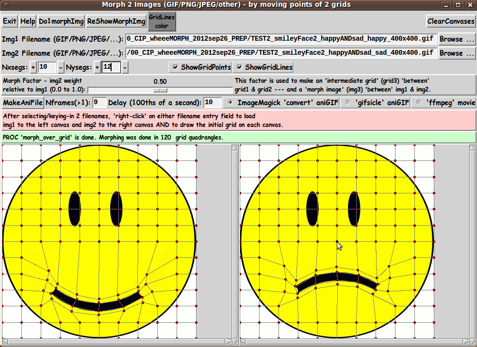
|
Below is a 'single morph' based on a 50-percent 'intermediate grid'. |
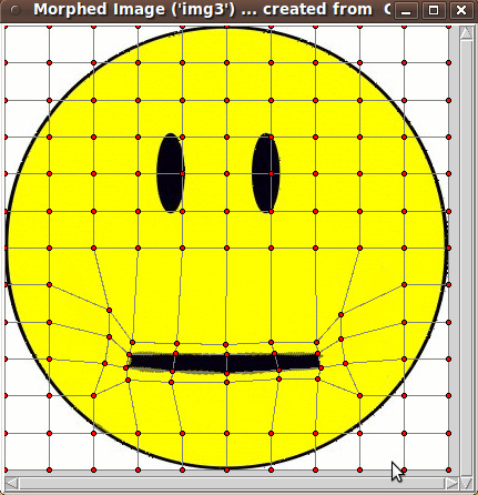
|
Note that there is a little bit of color-averaging (between black and yellow) showing around the 'lips'. It is hard to avoid this on an image like this without using a much finer grid. One thing that I found helped avoid too much of this fuzziness was to make the quadrangles just above and below the lips quite narrow --- close to the edges of the mouth. A resulting animated GIF did not turn out too badly --- but you can see the 'bleeding' of the black into the yellow, in the middle frames of the animation. |

|
Square to Circle I thought a challenging example would be to morph between a rectilinear object and a circular object. Below is an example in which I kept the color issues to a minimum by choosing two objects of similar color. |
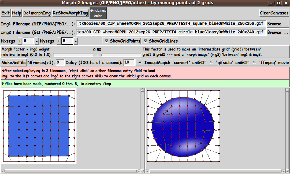
|
By using the grid above, I was able to generate a pretty good looking animation: |
|
A Hard-to-Morph-Nicely Example On the other hand, below are a couple of square and circular objects in which it is very difficult to map the colors of one nicely onto the colors of the other. |
|
I made a stab at it with the 2 grids shown above, and below is a resulting animation: |
|
There is a lot of 'bleeding' of black into white going on here.
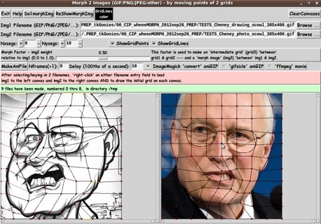
Morphing a Drawing to a Photo I thought I would try morphing between a drawing and a photo, as seen in the following 2 images and 2 deformed grids: |

|
The resulting animation turned up some surprises: |
|
The faces in the 2 images were turned at slightly different angles --- one facing somewhat to the left, the other looking almost straight ahead. I was rather surprised to see that the morph actually seems to make one head look like it is turning about the neck as one head morphs into the other. I was also pleasantly surprised at how smoothly the arched upper lip morphed from one image to the other. A Non-Human-Face and Human-Face Morph I have an old book 'Morphing on Your PC' (1994) by David K. Mason. It was one of my inspirations for writing this script --- especially since it had an old DOS 'DMorph' program on a (rigid) 'floppy disk' that was (probably) no longer runnable. (If it was still runnable on MS Windows 7 or 8, I was not going to waste time trying. I'd rather have my own Tcl-Tk utility.) I have long wanted to have a morphing program, so I wanted to make by own 'DMorph' program --- through the magic of Tcl-Tk. That seemed within my grasp after making the 'tkMerge2Images' and 'tkImageGridWarp' scripts mentioned at the top of this page. In the book, Mason points out some of the things to watch out for in choosing images and making the grids. One thing he pointed out is that it can be rather difficult to map between an human face and an animal face --- although you see it done frequently in movies nowadays. I wanted to see how hard it would be, so I chose the following 2 images: |
|
I wasn't very optimistic about the results that I could achieve with the 2 grids above, but I was pretty pleased with how the following animation turned out. |
|
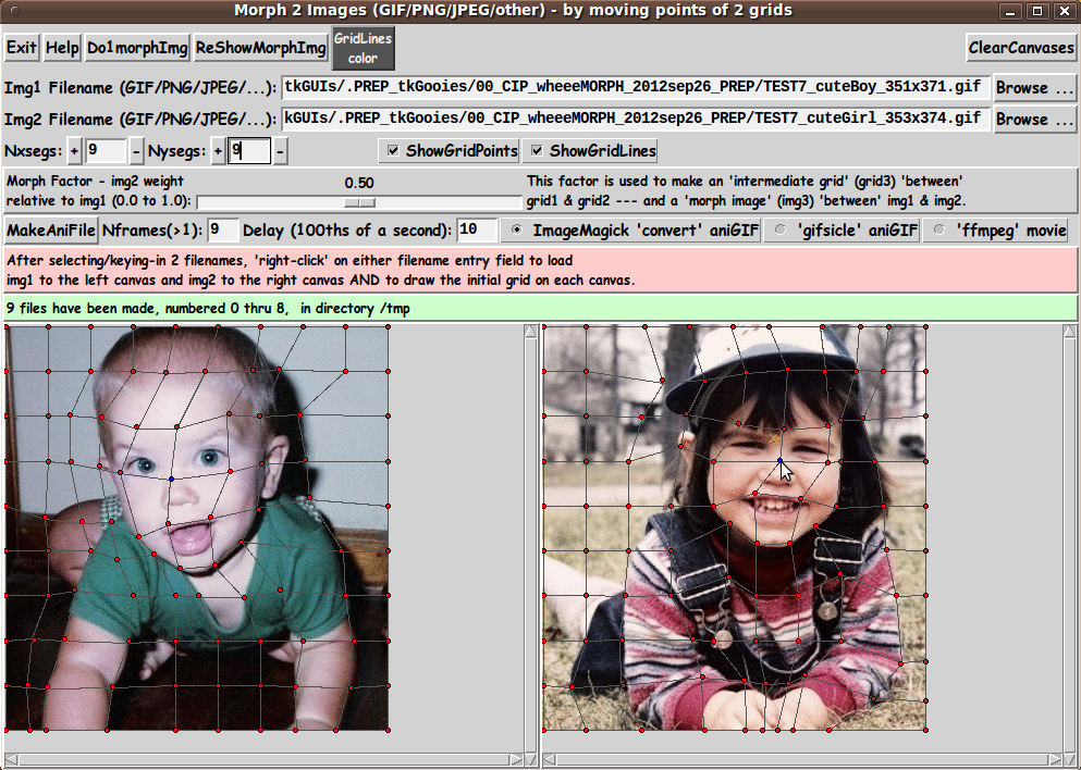
Considering I used only 9 frames, this seemed surprisingly good to me. In a few preliminary tests with more frames, I have found that using 30 frames (and a delay of about 3 100ths-of-a-second) can sometimes provide a more pleasing animation. Human to Human In looking at the examples above, one notices that there is no example of mapping one human face to another --- both in photos, rather than drawings. Below are a couple of images of that type. |
|
I used a rather crude grid to 'map' one image to the other --- basically eyes-to-eyes and mouth-to-mouth and arms-to-arms. However, it yielded the following animation (with only 9 frames), with which I was pretty pleased. |
|
If I used a finer grid and more frames in the animated-GIF, I could get a smoother 'movie'. But this is a challenging morph, because the head in the left image is tilted to the left and is on the left side of the photo --- whereas the head in the right image is straight up and on the right side of the photo. Also the hands in the left image are apart whereas the hands in the right image are together. Also there are a lot of color differences in the grid quadrangles (no matter how fine a grid I would use and no matter how 'expert' a mapping I could devise.) NOTE that this is not a simple graduated 'merging' of 2 images. The head of the left image actually 'warps' into the head of the right image --- that is, there is an actual left to right movement of portions of the images. Also the spread-apart forearms of the image on the left 'morph' (MOVE) into the forearms of the image on the right. Not bad. INSTALLING THE UTILITY/APP: The set of files for this utility consists of TWO Tk scripts:
and
Those two Tk scripts could be put in a sub-directory of the user's home directory --- such as $HOME/apps/wheeeMorph. Then the user can use his/her desktop system (such as Gnome or KDE) to set up the main Tk script as an icon on the desktop (or in a desktop 'panel'). Then, whenever the user wants to morph a pair of image files, the user can click on the icon to startup the Tk script. SOME POSSIBLE ENHANCEMENTS In using this utility over the next year, I may find that I would like to add a few capabilities, such as 1) Fine control of moving grid-points --- such as the ability to select a grid-point and then move it a pixel at a time with the arrow keys on the keyboard. 2) Ability to 'zoom' into a grid for placing points precisely. An even more enhanced script would allow for a background-color margin around the images and allow for pushing the 'edge' grid points 'outward' and 'inward'. ---
Handling All the Things I have tried quite a few different operations with the GUI, such as: * loading a pair of images, then a different (sized) pair of images * starting with the default grid, then changing Nxsegs and Nysegs * hiding and showing the grid points and lines --- the 'intermediate' grid (in the popup 'img3' window) as well as grids 1 and 2. I resolved quite a few issues in the process, but there are probably a few remaining. (I have not really tested the use of 'gifsicle' and 'ffmpeg' for making animation files.) However, I rejoice that 95% to 99% of the code is in place to achieve the goals I had in mind. Any further fixes and enhancements will probably feel like nothing compared to what I have been through in developing and testing this script. It rivals the amount of effort that I had to expend in developing the 3D model viewing script at
A 3D Model File Loader-and-Examiner - There is certainly a lot more challenge in creating a 'robust' interactive Tk script than there is in making a 'demo' Tk script in which a sequence of operations is basically hard-coded in the script --- thus making it unnecessary to handle essentially anything a user might do with a GUI that has quite a few control widgets on it. IN CONCLUSION As I have said on several other code-donation pages on this site ... There's a lot to like about a utility that is 'free freedom' --- that is, no-cost and open-source so that you can modify/enhance/fix it without having to wait for someone else to do it for you (which may be never). A BIG THANK YOU to Ousterhout for starting Tcl-Tk, and a BIG THANK YOU to the Tcl-Tk developers and maintainers who have kept the simply MAH-velous 'wish' interpreter going. |
|
Bottom of this page for To return to a previously visited web page location, click on the Back button of your web browser a sufficient number of times. OR, use the History-list option of your web browser. OR ...
< Go to Top of Page, above. >
|